Gathering the required items
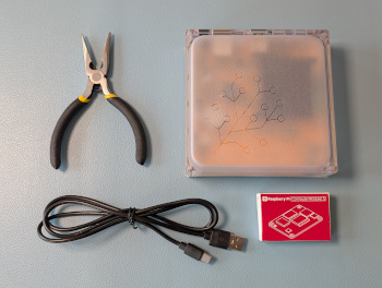
- Home Assistant Yellow installation with NVMe SSD drive and CM4 Lite
- Ethernet cable
Additionally, make sure you have the following items which are not part of the Kit
- Raspberry Pi Compute Module 5 Lite
- USB-C cable
- Heat sink: You can use the heat sink shipped with Yellow. If you want, you can also use the Raspberry Pi Compute Module 5 Passive Cooler. However, the Raspberry Pi Compute Module 5 Active Cooler is not supported on Home Assistant Yellow. There is no fan plug providing the required 5V and PWM signals.
- If you are using PoE, make sure your router or switch provides PoE on that port
- Optional: Power supply (12 V / 2 A, if PoE is not used)
- Flat nose pliers
Preparation steps:
- Make sure you installed Home Assistant Operating System version 14 or later.
- Make sure you have created a backup.
Opening the case
Step 1
Protecting from ESD
Grounding protects the components from the static electricity that can be naturally present (electrostatic discharge, ESD).
- Notice: Risk of damage to the equipment due to electrostatic discharge. Always: Touch the working surface before touching electronics.
- Ideally: Use ESD protective equipment, such as ESD table mats and grounding cords.
Step 2
Removing the case - bottom part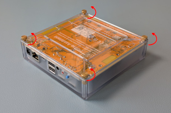
- Remove the 4 screws on the bottom of the Home Assistant Yellow Kit.
- Keep the thumb screws close by; you will need them again later.
Step 3
Removing the case - top part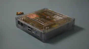
- Make sure the interfaces are facing towards your left.
- Flip the case over.
- Slightly lift off the enclosure on your left.
- Slide the enclosure off towards your right.
Removing the Raspberry Pi Compute Module
Step 1
Removing the heat sink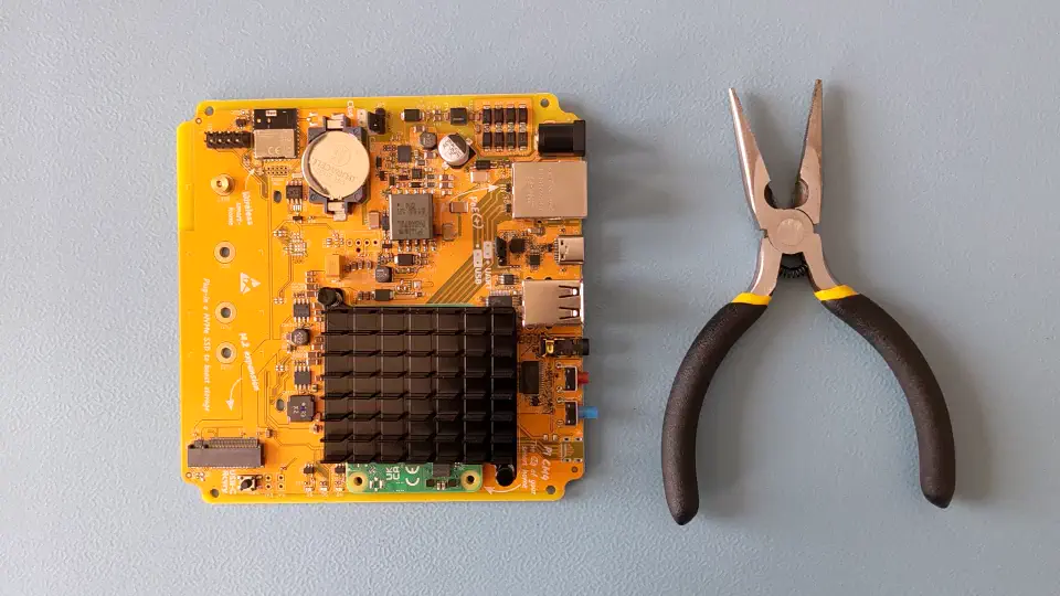
- Use the pliers and squeeze the front of the pin so that it fits through the hole.
- Repeat the procedure for the other pin.
Step 2
Removing the Raspberry Pi Compute Module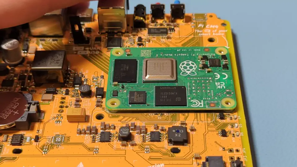
- Info: The image shows a Raspberry Pi Compute Module 4. The steps are the same for the Compute Module 5.
- Notice: To avoid damage to the module, ideally, the module should be pulled up vertically. But this is hard to do.
- Pull up the module from one side, tilting as little as possible. Tilting can damage the connector.
- Info: This requires quite a bit of force. If it does not work, pull harder.
- Notice: Do not use a screw driver as a lever. It might damage the board.
Seating the Raspberry Pi Compute Module 5
Step 1
Align the Compute Module
- Place the board in front of you, the red and blue buttons facing to the right.
- Orient the CM5: The Raspberry Pi text needs to be on the right hand side.
- Carefully place the CM5 without force.
- The CM5 should fall into place slightly when correctly aligned.
Step 2
Installing the CM5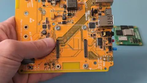
Notice: Risk of damage to equipment Don't use screws to fix the module in place. The screws can damage the components on the CM5 module.
Screws are provided for optional use with the CM4 module only.
- Press the Compute Module 5 onto the board-to-board connectors until it clicks into place.
- Make sure you press on both sides (the two long edges).
- This requires quite a bit of force. If you don't hear a loud click, it is most likely not fully seated.
- It has been reported that on some boards, there is no click sound when pressing the module onto the board. It can still be seated correctly.
- Do a visual check to make sure the module is installed correctly: it needs to run parallel to the Home Assistant Yellow board. You can also pull a bit on the sides to make sure it is not loose.
Notice: Risk of damage to equipment Don't use screws to fix the module in place. The screws can damage the components on the CM5 module.
Screws are provided for optional use with the CM4 module only.
Step 3
Placing the thermal pads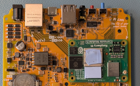
- Place the square thermal pad on the silver CPU.
- Place the rectangular thermal pad on the black rectangular chip.
Step 4
Placing the heat sink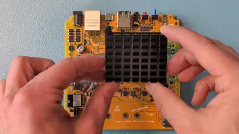
- Push the 2 plastic push pins into the dedicated hole on the heat sink.
- Start by first aligning the right plastic push pins into the dedicated hole on the carrier board.
- Then, place the heat sink onto the module.
Step 5
Securing the heat sink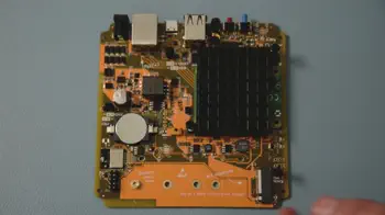
- Take the entire board off your workplace and push the pins firmly through the carrier board.
- Ensure that the module is still fully seated after securing the heat sink.
Reassembling your Home Assistant Yellow
Step 1
Preparation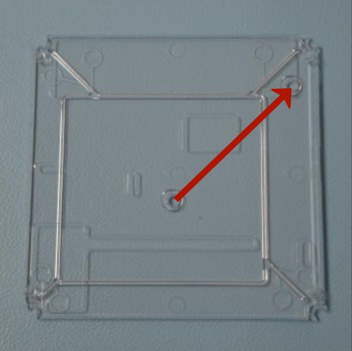
- Place the translucent bottom part of the case onto the table.
- Make sure the two round notches form a line pointing towards the top right corner.
Step 2
Reassembling - bottom part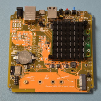
- Place the board onto the bottom part of the case.
- Make sure the USB connectors are facing upwards, away from you.
Step 3
Reassembling - top part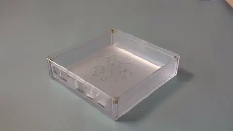
- Turn the enclosure upside down.
- Then, slide the push buttons into the openings of the case.
Step 4
Mounting the case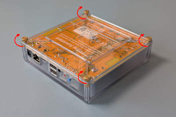
- Insert the 4 thumb screws.
- Notice: Risk of damage to the equipment due to excessive force. Do not over-tighten the screws.
Powering up
Step 1
Power up your Home Assistant Yellow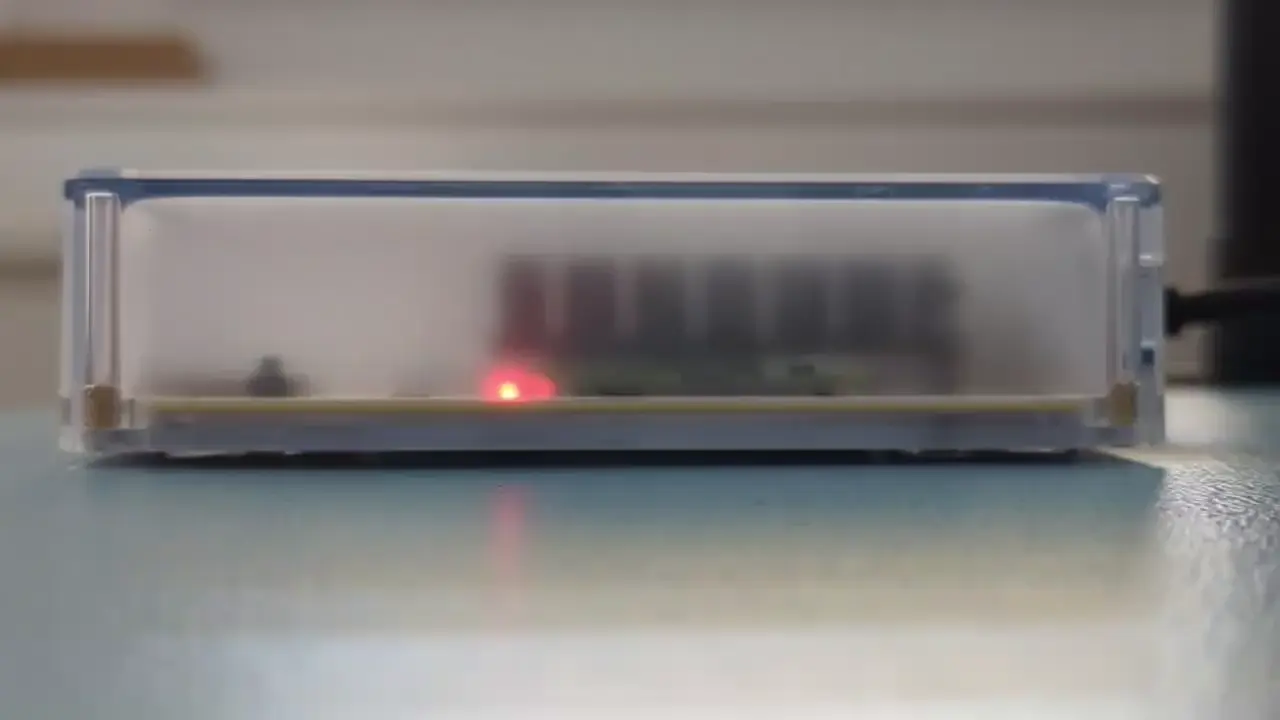
- Connect Ethernet and power.
- Start up may take a while. Once the yellow LED blinks in a heartbeat pattern, the system is up and running.
Step 2
Getting started with Home Assistant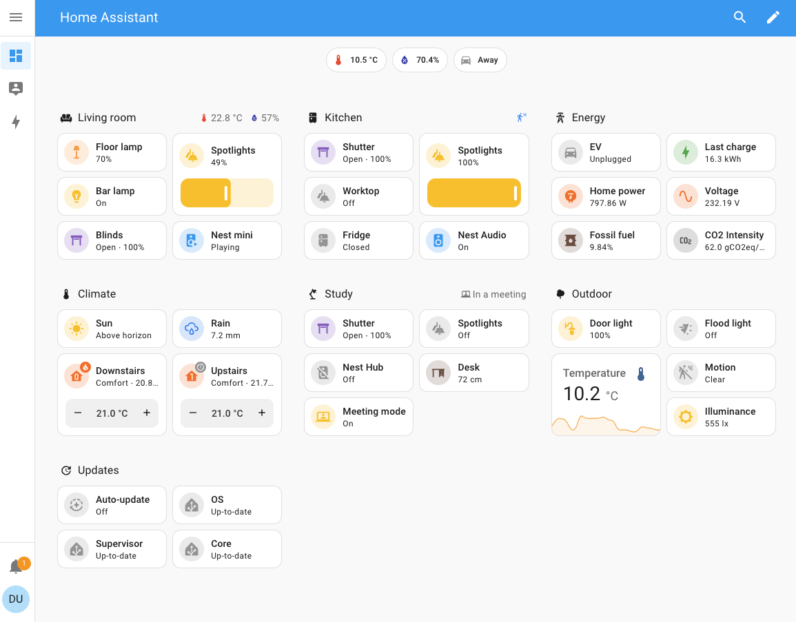
- Open Home Assistant:
- Visit http://homeassistant.local:8123 to access the Home Assistant frontend.
- As your data is stored on the NVMe, your dashboard comes up as usual. No additional steps required.