Gathering the required items
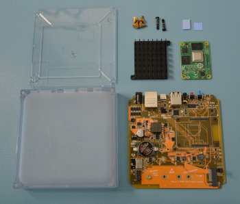
- 1 Raspberry Pi Compute Module 4 (CM4)
- 1 heat sink
- 2 thermal pads
- 2 push pins
Opening the case
Step 1
Protecting from ESD
Grounding protects the components from the static electricity that can be naturally present (electrostatic discharge, ESD).
- Notice: Risk of damage to the equipment due to electrostatic discharge. Always: Touch the working surface before touching electronics.
- Ideally: Use ESD protective equipment, such as ESD table mats and grounding cords.
Step 2
Removing the case - bottom part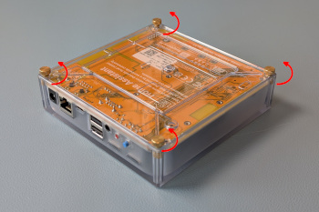
- Remove the 4 screws on the bottom of the Home Assistant Yellow Kit.
- Keep the thumb screws close by; you will need them again later.
Step 3
Removing the case - top part
- Make sure the interfaces are facing towards your left.
- Flip the case over.
- Slightly lift off the enclosure on your left.
- Slide the enclosure off towards your right.
Installing the Raspberry Pi Compute Module 4
Step 1
Unpacking the components- Make sure you have all the components:
- 1 Raspberry Pi Compute Module 4 (CM4)
- 1 heat sink
- 2 thermal pads
- 2 push pins
Step 2
Align the CM4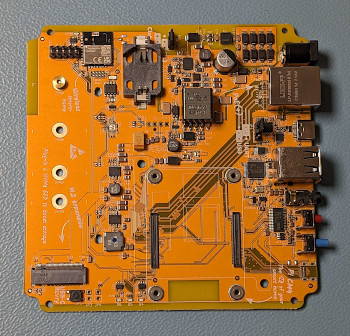
- Place the board in front of you, the connectors facing to the right.
- Orient the CM4: The CE mark needs to be on the bottom.
- Use the outline of the chips to help find the correct orientation of the CM4. Note: on CM4 Lite variants, the chips on the bottom edge are in a different location.
- Carefully place the CM4 without force.
- The CM4 should fall into place slightly when correctly aligned.
Step 3
Installing the CM4
- Press the CM4 board onto the board-to-board connectors until it clicks into place.
- Make sure you press on both sides (the two long edges).
- This requires quite a bit of force. If you don't hear a loud click, it is most likely not fully seated.
- Do a visual check to make sure the CM4 is installed correctly: it needs to run parallel to the Home Assistant Yellow board.
Step 4
Placing the thermal pads onto the CM4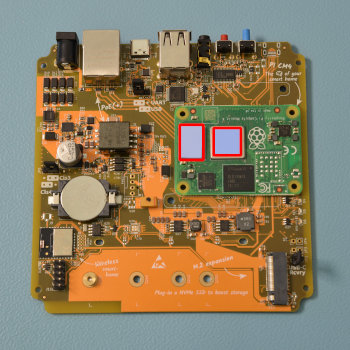
- Remove the protective cover from one side of the square thermal pad.
- Stick the unprotected side onto the SOC (the silver square next to the raspberry icon).
- Remove the protective cover from the top side of the thermal pad.
- Repeat the steps with the rectangular thermal pad. Place it on the memory (the black rectangle next to the SOC).
Step 5
Placing the heat sink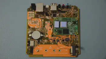
- Push the 2 plastic push pins into the dedicated hole on the heat sink.
- Start by first aligning the right plastic push pins into the dedicated hole on the carrier board.
- Then, place the heat sink onto the CM4.
Step 6
Securing the heat sink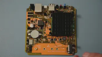
- Take the entire board off your workplace and push the pins firmly through the carrier board.
- Ensure that the CM4 is still fully seated after securing the heat sink.
Reassembling your Home Assistant Yellow
Step 1
Preparation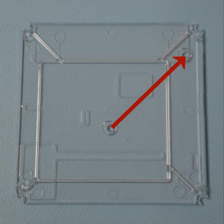
- Place the translucent bottom part of the case onto the table.
- Make sure the two round notches form a line pointing towards the top right corner.
Step 2
Reassembling - bottom part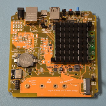
- Place the board onto the bottom part of the case.
- Make sure the USB connectors are facing upwards, away from you.
Step 3
Reassembling - top part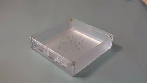
- Turn the enclosure upside down.
- Then, slide the push buttons into the openings of the case.
Step 4
Mounting the case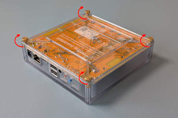
- Insert the 4 thumb screws.
- Notice: Risk of damage to the equipment due to excessive force. Do not over-tighten the screws.